Fitting a mesh interface with SWIFT
Define an implicit circle, mark a mesh interface and fit it with a P1 displacement.
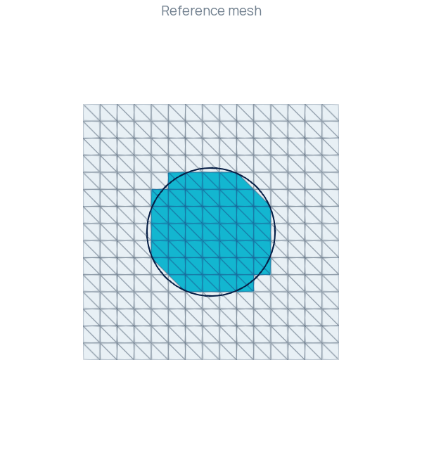
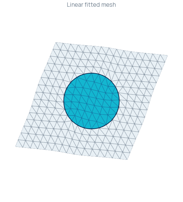
This tutorial constructs a triangular mesh of the unit square, marks an internal polygonal interface and moves that interface towards a circle. A vector-valued displacement moves the vertices while retaining the mesh connectivity. The complete program is available in InterfaceFitting.cpp.
SWIFT fits selected mesh facets to the zero set of a supplied function. Its fitting force is distributed through the surrounding mesh, with deformation-quality checks during step acceptance. The SWIFT namespace reference explains the mathematical construction and solver parameters.
1. Create the background mesh
The example uses local Eigen-backed storage. Its main headers and namespace aliases introduce the types used in the example.
#include <Rodin/Adaptation.h>
#include <Rodin/Geometry.h>
#include <Rodin/IO/XDMF.h>
#include <Rodin/QF/QuadratureFormula.h>
#include <Rodin/Variational.h>

using namespace Rodin;
using namespace Rodin::Geometry;
using namespace Rodin::Variational;
namespace SWIFT = Rodin::Adaptation::SWIFT;
A grid with 16 vertices per axis contains 450 triangles. Scaling by gives the physical domain . Connectivity is prepared before cell classification and interface integration.
    constexpr size_t PointsPerAxis = 16;
    constexpr Real h = Real(1) / (PointsPerAxis - 1);
    constexpr Attribute Inside = 1, Outside = 2, Interface = 10;
    auto mesh =
      LocalMesh::UniformGrid(Polytope::Type::Triangle, {PointsPerAxis, PointsPerAxis});
    mesh.scale(h);
    for (size_t from = 0; from <= 2; ++from)
    {
      for (size_t to = 0; to <= 2; ++to)
        mesh.getConnectivity().compute(from, to);
    }
Cell attributes Inside and Outside distinguish the two regions. The facet attribute Interface selects the edges to fit. These labels identify entities of different dimensions.
2. Define the target interface
The target is the circle with center and radius . Its implicit function and gradient are
Negative values identify the interior. Both functions are evaluated in physical coordinates, including displaced points during fitting.
    constexpr Real Radius = Real(0.25);
    RealFunction phi([](const Point& point) {
      return std::hypot(point.x() - Real(0.5), point.y() - Real(0.5)) - Radius;
    });
    VectorFunction gradient(2, [](const Point& point) {
      Math::SpatialVector<Real> radial(2);
      radial(0) = point.x() - Real(0.5);
      radial(1) = point.y() - Real(0.5);
      const Real length = radial.norm();
      if (length == 0)
        return Math::SpatialVector<Real>::Zero(2);
      return Math::SpatialVector<Real>(radial / length);
    });
The gradient has a zero fallback at the center, where radial distance is nondifferentiable. The target interface lies a positive distance from that point. Replacing the target requires a consistent gradient as well as a new implicit function.
3. Mark a starting mesh interface
The initial interface must consist of existing mesh edges. MinSTCut classifies triangles using a cell average of a smoothed sign of . Its cut edges separate the two resulting cell sets.
    // Dimensionless phase width and smoothing for this unit-square example.
    constexpr Real PhaseWidth = Real(1.25), Smoothing = Real(0.01);
    constexpr size_t ClassificationOrder = 2;
    MinSTCut classifier(mesh);
    decltype(classifier)::Parameters classification;
    classification.smoothing = [](const Polytope&) { return Smoothing * h; };
    classifier.setParameters(classification);
    const auto labels = classifier.classify([&](const Polytope& cell) {
      const auto& formula =
        QF::QuadratureFormula::get(ClassificationOrder, cell.getGeometry());
      const auto& quadrature = cell.getQuadrature(formula);
      Real moment = 0;
      for (size_t q = 0; q < quadrature.getSize(); ++q)
      {
        const auto& point = quadrature.getPoint(q);
        moment += formula.getWeight(q) * point.getDistortion() *
          std::tanh(phi(point) / (PhaseWidth * h));
      }
      return moment / cell.getMeasure();
    });
    for (const Index cell : labels.inside)
      mesh.setAttribute({2, cell}, Inside);
    for (const Index cell : labels.outside)
      mesh.setAttribute({2, cell}, Outside);
    for (const Index edge : labels.cut)
      mesh.setAttribute({1, edge}, Interface);
The phase width and smoothing weight are choices for this background mesh. The quadrature loop computes the cell-average input; the following loops attach the returned labels to the mesh. Fitting then changes coordinates while preserving those labels and the connectivity.
4. Solve for a P1 displacement
A two-component space represents the displacement . Trial and test functions provide the variational interface to SWIFT::Problem.
    P1 vh(mesh, 2);
    TrialFunction u(vh);
    TestFunction v(vh);
    SWIFT::Problem fitting(u, v);
    SWIFT::Parameters parameters;
    parameters.model.h = h;
    parameters.linear.solver = SWIFT::Parameters::LinearSolver::SparseLU;
    fitting.setParameters(parameters).setInterfaceAttribute(Interface);
    const auto report = fitting.solve(phi, gradient);
model.h is the reference mesh spacing. The example explicitly selects SparseLU for its small local system. setInterfaceAttribute(Interface) selects the marked internal edges, and solve(phi, gradient) stores the accumulated displacement in u.getSolution().
The outer square is free to move in this program. A fixed-boundary variant can add a vector DirichletBC on separately marked exterior facets; the MMG–SWIFT tutorial demonstrates that setup. The mesh, finite-element space and trial/test functions remain alive throughout the solve and displacement evaluation.
5. Check the result before moving the mesh
The solver report separates reaching the geometric target from satisfying the sampled deformation-quality budget. Both are required by this program.
    std::cout << std::setprecision(12) << "exit=" << report.getReasonString()
              << " target_hit=" << report.geometricTargetReached
              << " quality_ok=" << report.qualityBudgetSatisfied
              << " D_inf=" << report.geometricSup
              << " target=" << report.geometricSupTarget << " min_j=" << report.minJ
              << " max_Q=" << report.maxQRel << " outer=" << report.iterations << '\n';
    if (!report.geometricTargetReached || !report.qualityBudgetSatisfied)
      return EXIT_FAILURE;
D_inf is the maximum sampled gradient-normalized level-set residual. For this signed-distance target it measures radial error at the validation points. The automatic target is . min_j and max_Q describe the sampled relative deformation Jacobian and distortion. The report reference defines these fields and the termination reasons.
In the checked run, the sampled radial error was approximately , below . An independent calculation over complete fitted edge segments gave the same maximum radial error. All 450 moved triangles had positive signed Jacobians, and their connectivity was unchanged.
6. Apply the displacement and export
A separate mesh retains the fitted coordinates. Each vertex displacement is evaluated on the unchanged reference mesh.
    LocalMesh moved(mesh);
    const auto& displacement = u.getSolution();
    for (auto vertex = mesh.getVertex(); vertex; ++vertex)
    {
      const Point point(*vertex, Polytope::Traits(Polytope::Type::Point).getVertex(0));
      moved.setVertexCoordinates(vertex->getIndex(),
        point.getPhysicalCoordinates() + displacement.getValue(point));
    }
For affine triangles and displacement, these vertex updates fully define the moved mesh geometry. The operation retains the 450 triangles and their incidence relations.
    IO::XDMF output("InterfaceFitting");
    output.grid("background").setMesh(mesh).add("displacement", displacement);
    output.grid("moved").setMesh(moved);
    output.write().close();
InterfaceFitting.xdmf contains the reference background block with its displacement field and the fitted moved block. Keep the HDF5 files beside the XDMF description. In ParaView, select Extract Block, choose moved, enable Surface With Edges and color by the cell field Attribute.
Build and run
Use a configured local build with examples enabled. The installation guide describes the dependencies. This example generates its mesh and needs no resource download or MMG step.
cmake --build build --target SWIFT_InterfaceFitting
mkdir -p results/swift-p1
cd results/swift-p1
../../build/examples/Adaptation/SWIFT/SWIFT_InterfaceFitting
The executable returns failure when either the geometric target or the sampled quality budget is missed. The printed report and generated mesh provide the fit and geometry checks for a repeated run.
Extension to P2
SWIFT also supports displacement. The quadratic reconstruction example uses the same circle and background resolution, evaluates the solved field at every quadratic geometry node and retains the resulting curved transformations. The figure below shows that computed result.
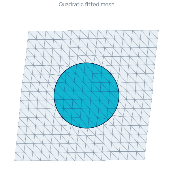
Higher-order geometry requires updating its edge and cell geometry nodes along with its vertices. The complete implementation is in Reconstruction.cpp; the namespace reference supplies the model, parameter definitions and sampling policies.
Complete source
InterfaceFitting.cpp contains the complete P1 program. For background remeshing and fixed exterior vertices, continue with Adapting and fitting an implicit interface.